RASC-AL Exploration Robo-Ops Competition (i.e., Robo-Ops) is an engineering competition sponsored by NASA and organized by the National Institute of Aerospace. In this exciting competition, undergraduate and graduate students are invited to create a multi-disciplinary team to build a planetary rover prototype and demonstrate its capabilities to perform a series of competitive tasks in field tests at the NASA Johnson Space Centers Rock Yard in June 2013.
We were fortunate to be given the opportunity to show off some of the leading entries into the RASC-AL Exploration Robo-Ops Competition. Here are 5 of the design reports:
Worcester Polytechnic Institute
University of Nebraska-Lincoln
FAMU/FSU College of Engineering
Student Team
Timothy Godisart (lead), Jason Battin, Benjamin Carrero, Marc Gramlich, Benjamin Knabenshue, Yuan Li, Michael Martin, John Perrine, Mark Pitts, Kyle Swisher
Faculty Advisor
Dr. Powsiri Klinkhachorn
Executive Summary
The West Virginia University Mountaineers robotics team was one of the eight recipients selected to participate in the design and construction of an interplanetary rover for the 2012 RASC-AL Exploration Robo-Ops Student Challenge. The team successfully built a robust, well-functioning rocker-bogie suspension system rover. Despite being one of the rookie teams, the Mountaineers finished 4th overall in the competition. The team, if given an opportunity, believes the lessons learned from the 2012 competition in both hardware and software design coupled with comprehensive operational procedures and protocols will help the team excel in the upcoming 2013 competition. The foundation of the 2013 proposed rover will be the proven rocker-bogie suspension system. The selected system is superior to others and will allow the rover to reliably traverse rocky terrain and climb steep slopes per mission requirements. The proposed rover design leverages new features such as a lighter but just as solid chassis and suspension system, a light weight but high torque low energy consumption drivetrain, newly designed rover wheels for higher traction while at operating speed, and coupled with additional software development for semi-autonomous navigation, sample detection, and more efficient communication system. The rover will be equipped with a lightweight robotic arm with four degrees of freedom to effectively acquire and store samples during the exploration. A low-power processor with sufficient computing power will be used to perform basic control functions, sensor acquisition, semi-autonomous sample locator, and communication. Navigation will be performed using a GPS, several stationary cameras, and an Inertial Measurement Unit (IMU). The power source will be delivered from lightweight, high energy density, Lithium batteries. Several components of the new design have been tested and validated for their functionality to meet the required goals. The proposed rover shall weigh approximately 35 Kg versus 45 Kg from the 2012 rover.
The Mountaineers' team is comprises both graduate and undergraduate students in a variety of disciplines. Several members of this year’s team were also part of the 2012 RASC-AL Exploration Robo-Ops Student Challenge competition. A portion of the team participated in the previous two NASA Lunabotics Mining Competitions, in which the Mountaineers were the only team to place in the top three for the Joe Kosmo Award for Excellence, Grand Prize, both years among other awards. The Mountaineers are also in collaboration with Bluefield State College, a minority institution, to help the team to extend its STEM outreach programs to the southern part of the state. The team has full endorsement and commitment to provide additional financial support from the Statler College of Engineering and Mineral Resources, the Department of Computer Science and Electrical Engineering, the WV NASA Space Grant Consortium, and the Department of Mechanical and Aerospace Engineering.
Introduction
The importance of robotics in space research has never been greater. As mission complexity and duration exceed the physical capabilities and limitations of human astronauts, the only logical solution is to employ the use of robotics. Using robots on the front-line of space exploration facilitates longer mission durations, eliminates humans from danger, and reduces costs. Whether a rover is operated remotely or autonomously, their usefulness in accelerating space exploration has been proven many times over the past several years, especially with the rover, Spirit, Opportunity, and Curiosity currently on Mars missions. The opportunity to develop new rover technologies and utilize them in new ways is only increasing.
This paper will showcase the Mountaineers’ ability to compete in this competition and will introduce the proposed rover design. The remainder of this paper will be divided into four sections: system requirements and description, project management, communication plan and lessons learned.
System Requirements and Description
The system design is directly derived from the system requirements. The system requirements are based on the NASA/NIA Planetary Rover Design Requirements, Rock Yard Users Guide and Project Evaluation Criteria and Scoring Approach.
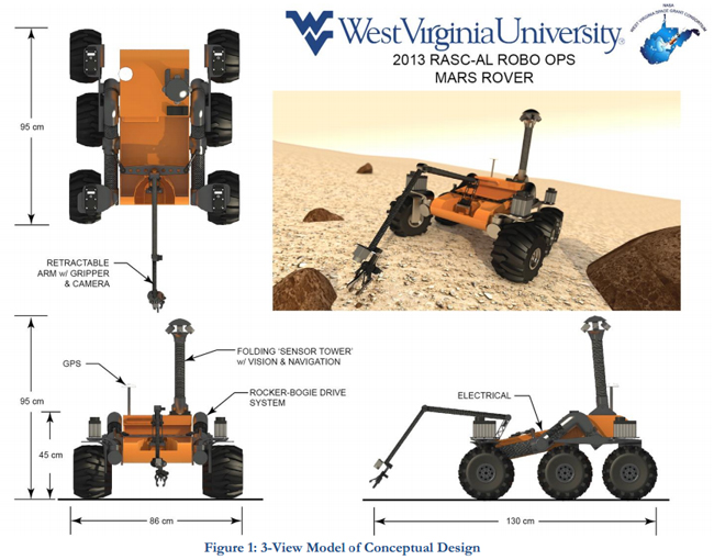
The proposed conceptual design, incorporating the rocker-bogie suspension as well as the gripping arm and collection bin, is depicted in Figure 1. In this rendering, it can be seen that the design incorporates wide wheels with deep grooved rubber tires to allow the vehicle to achieve better traction in the loose terrain. Multiple cameras are deployed on the vehicle’s sensory tower for environmental sample locator. Additional forward looking wide angle lensed camera and gripper camera are also equipped to assist in the remote driving and sample acquisition.
Chassis Design
There are a multitude of factors to consider when developing a rover for an interplanetary mission. The remoteness, lack of onsite repair, and rugged, unpredictable terrain of the environment strongly impact the engineers’ design. The chassis is one of the largest and most critical components of any interplanetary rover. The chassis consists of four main subsystems: frame, suspension, drivetrain, and steering. The frame must be strong enough to handle the rigors of traversing the obstacle field with a full payload; however, it must also be light enough to minimize power consumption and fulfill the mass requirement. A trade-off analysis was performed on various chassis materials. The analysis explored the cost of material versus its strength and mass to ensure system mass satisfies the 45 Kg requirement. Aluminum alloys and carbon fiber composites were shown to provide the best compromise. The proposed design achieves rollover stability by incorporating a low center-of-gravity with a wide wheelbase.
Suspension System Design
A suspension system improves the rover’s ability to reliably traverse rocky terrain and climb steep slopes. Among possible suspension system designs, the rocker-bogie configuration has been proven to be one of the most robust systems at adapting to harsh terrain; this design has been validated by the Mars Curiosity rover, as well as the team’s entry for the 2012 competition. The rocker-bogie system does not use springs or pressurized elements, such as hydraulics or pneumatics, which makes the chassis more viable in most environments encountered during space exploration. It utilizes a sixwheel independent drive configuration, employing kinematics to maximize traction and can be attached to almost any frame design. The proposed wheel diameter is 25 cm providing ample ground clearance to negotiate 10 cm obstacles per system requirements. The rocker-bogie suspension system provided an excellent platform for the design during the 2012 competition and will continue to be a solid foundation for this year’s design.
Drivetrain Design
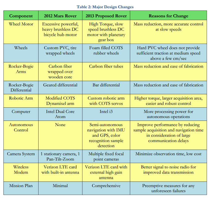
The rover’s propulsion is provided from brushless DC motors, 540 series, with a high torque, slow speed planetary gearboxes. This type of motor is commonly used in scale model RC rock crawlers for its high torque and relatively low speed. The new motor gearbox combination will significantly reduce the new rover’s mass by almost 10 Kg over the 2012 rover. The brushless DC bicycle hub motors utilized in the previous design were over-designed. While very powerful, they were also too heavy, and did not provide adequate control at low speeds. Additionally, the new drivetrain will provide much greater controllability for both low and high speeds. Preliminary testing provides a high-level of confidence that six motors can deliver more than adequate torque to propel the robot over the challenging terrain with a high degree of agility, fault tolerance, and drive redundancy.
.jpg) Wheels
Wheels
The wheels chosen this year are COTS foam filled rubber wheels which are 25 cm in diameter and 14.6 cm wide shown in Figure 2. The tire has been specifically designed for rock climbing applications and thus provides a high level of traction. The previous wheels were made of hard PVC material and did not provide adequate traction on the rocky terrain at the standard operating speed. During preliminary testing the new wheels have provided enough traction to climb stairs and traverse several different obstacles.
Steering System Design
Another key design requirement for developing a suitable chassis is maneuverability. The rockerbogie chassis features an independently driven and controlled wheel configuration that allows for highly adaptable control and mobility. The maneuverability of this design is due in part to four powerful steering servomechanisms attached to the front and rear wheels of the robot, seen in Figure 1. This provides a zero turning radius and allows them to be easily rotated to avoid impediments. The steering system will be similar to 2012 design due to its proven reliability.
Robot Arm
The previous rover utilized a 6-degrees of freedom (DOF) robotic arm. This gave the arm great maneuverability but two of the DOF were rarely used and caused the arm control to be over complicated. The new proposed arm will have 4 DOF to effectively achieve the requirement of retrieving targeted sample rocks: 2 DOF about the Z-axis are needed for placing the sample into a collection bin, while 1 additional DOF will be added with the integration of a rotating. The final DOF will be the used to grasp the sample.
The robotic arm, shown in Figure 1, will be mounted at the front-side of the rover platform facing forward. A camera will be mounted above the grabber section of the robotic arm so that images corresponding to the attitude and position of the arm are sent back to the user station.
A collection bin will be incorporated for storing retrieved samples. The volume shall be large enough to meet the objective requirement of collecting 30 samples and safely stow them for transportation back to the collection area.
Electronics
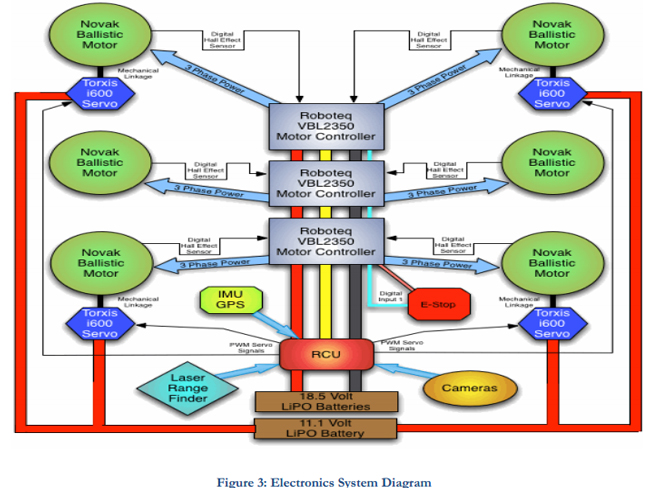
The electronics subsystem is divided into several key components that work in unison to provide a stable control system for the rover. Lithium polymer (LiPo) batteries will be used due to their high energy to weight ratio. Figure 3 provides an overview of the electronics subsystem.
Onboard Computing
The rover employs an on-board computer that performs the essential tasks of the rover’s control system. These tasks include providing a robust control interface for servo and motor controllers, monitoring the robot’s state-of-health, adapting robot performance to environmental conditions, performing semi-autonomous sample detection, and implementing autonomous self-sustaining protocols during terrestrial loss of communication. The proposed computer is of mini-ITX formfactor and features a low-power-consumption processor (2.6 GHz Intel i3).
Communication
A reliable communication system is crucial to the operation of an interplanetary rover. Since the robot and its operators are separated by over a thousand miles, a stable link between them is critical. From the team's experience, a Verizon Wireless broadband modem card provided adequate bandwidth and a reliable connection. This card will be used once again with the addition of an external high gain antenna to increase the signal to noise ratio.
Sensory
The rover will utilize many sensors for situational awareness. It was determined from seeing how other team’s operated in the past that the use of multiple cameras is very valuable for control purposes. The use of several fixed cameras allows the operator to select between multiple different stationary camera views. A laser rangefinder and other optical sensors will be used to assist in providing an accurate spatial awareness of surrounding obstacles. A GPS will also be used to provide an accurate location of the rover. This sensory information will be displayed to the operator in an overlay of the robot on satellite imagery of the rock yard.
Programming
The software for the rover will be divided into two components: the Operator Control Unit (OCU) and the Robot Control Unit (RCU). The OCU software has two main tasks: process user input to control the state of the rover and display telemetry feedback from the RCU. The OCU will be designed for three operators: the rover driver, camera selector and the sample acquisition system operator. Each user has their own interface and works in concert to achieve mission objectives. The RCU has three key tasks: receive input from the OCU, perform autonomous operations, and process feedback telemetry data.
Autonomy
Tele-operation poses a considerable challenge due to operator awareness being hindered by communication latency issues, which increases the difficulty of controlling the robot. The feedback delay limits the ability to perform precise operations, and can lead to undesirable conditions. To counteract the latency issue, various autonomous capabilities will be developed to both assist in the operation of the robot, as well as prevent the operator from performing actions that pose a hazard to the rover.
Navigation Assistance
The primary navigation method for the rover is teleoperation, based on imagery transmitted from the onboard cameras. However, due to communication latency, controlling the rover in real-time is impossible. The rover employs a navigational assistance system (NAS), which provides a precise state vector including global position, three-axis velocity, and three axis attitude. This data allows the operator to know where the rover is in the operating environment as well as provide a goal position to be navigated to autonomously. Furthermore, the inertial data provides a means to check for wheel slippage by detecting a difference in speed reported at the wheels versus speed reported by the NAS. The NAS fuses data from an IMU and a GPS using an extended Kalman filter (EKF). The EKF calibrates the IMU-provided estimates of three-dimensional positions and velocities with data from the GPS. It also derives attitude utilizing the IMU’s three-axis gyroscopes and accelerometers. This data is reported periodically as telemetry and used on-board for point-to-point navigation.
 Sample Detection and Acquisition Assistance
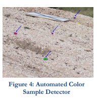
Several color-detecting cameras will be mounted on the robot to assist in locating samples. Using different image processing techniques, camera views provided to the operator would have any rock specimens highlighted to provide better awareness of the samples as shown in the Figure 4.
Acquisition of rock samples requires precise control of the robotic arm. Due to lengthy communication delays, manual robotic arm control is a time consuming and arduous process. To expedite the collection process, some semi-autonomous control will be implemented.
Project Management
Team
The Mountaineers' team is composed of several experienced members with a variety of skills. A portion of the team participated in the 2012 RASC-AL Exploration Robo-Ops Student Challenge competition, as well as the 2011 and 2012 NASA Lunabotics Mining competitions. The Mountaineers have a history of excellence in these competitions by winning several awards and placing high in the overall competitions. Participation in these competitions has provided a foundation of organizational and design skills essential to successfully compete in the RASC-AL Exploration Robo-Ops Student Challenge. In addition, the team comprises a diverse group of students, both undergraduate and graduate, in the areas of aerospace, computer, electrical, industrial, and mechanical engineering, and computer science. The team’s engineering faculty advisor was also the advisor for the Lunabotics competitions, as well as a ten-year supporter of the FIRST Robotics Program and an avid robotics enthusiast with over 30 years of robotics experience. Furthermore, the team is partnering with the Air Force ROTC Detachment 915 at West Virginia University. Several ROTC cadets are participating, in conjunction with several non-technical cadets in providing support for outreach and project management. The Mountaineers are also in collaboration with Bluefield State College, a minority institution, for helping the team to extend our STEM outreach programs to the southern part of the state.
Facilities
West Virginia University’s Statler College of Engineering and Mineral Resources offers laboratories, machine shops (Figure 5), and technicians that cover the gamut of metal, composite materials, 3D printing and printed circuit board fabrication as well as other technologies key to the success of building an interplanetary rover analog. In addition, NASA’s IV&V facility, located near the engineering campus, offers a Planetary Surface Simulation Lab, Figure 6, which provides end-toend mission testing capabilities.

 Budget
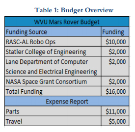
The budget is divided into two categories: rover parts/fabrication and travel. Table 1 shows the organization of the budget. The budget funds comprise the $10,000 stipend from RASC-AL Robo-Ops and funding from various sources at West Virginia University and WV NASA Space grant. Additional funding can be obtained if deemed to be necessary through fundraising proceeds.
The management of project funds is a critical element to the success of the project. The team will appoint a student as Chief Financial officer (CFO) to manage the budget though established funding processes. The CFO will be responsible for managing purchases, validating requirement of purchase, funds, fundraising, and making weekly reports to the faculty advisor.
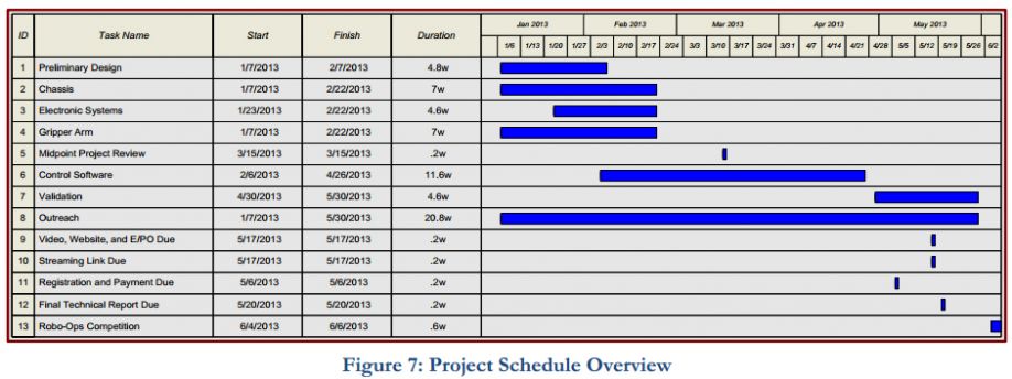
Schedule
The team has created a schedule to help organize the design process and ensure that the design is completed in a timely manner. A scheduling officer has been appointed to keep track of the team’s progress and maintain a strict timeline.
Communications Plan
Outreach and Social Media
One of the goals of the team is to engage the community through outreach. The team will be collaborating with local high schools and technical colleges to increase interest in science, technology, engineering, and math (STEM) fields and help them develop meaningful skills and experiences. In an attempt to spread the team’s outreach across the state, the team is partnering with Bluefield State College. Students from BSU will receive training from the team and will engage the community in the southern part of West Virginia.
The team will utilize social media through several outlets, namely Facebook, Twitter, and Tumblr. These services can keep our team in contact with a wide variety of people and generate a large audience. The Tumblr page will serve as a blog and will be the main source of information. Facebook and Twitter will act as a mirror for that information and allow our audience to share the information with their friends and peers. The team will also involve several local news media outlets, including WBOY-TV News, the WVU campus newspaper The Daily Athenaeum, and the local newspaper The Dominion Post. These media outlets have previously participated in covering the progress and achievements of the RASC-AL Robo-Ops and Lunabotics teams.
Lessons Learned
The team's experience at the 2012 RASC-AL Robo-Ops competition provided great insight on how to improve our rover and mission operation. Most importantly, mission plans need to be developed for the operators, similar to those used by NASA. These mission plans should establish strict protocols on how to react to any unforeseen failures. These plans are critical due to the lack of communication between the on-site team and the operators. A full system test procedure will be produced and performed prior to the competition run. The team's rover suffered a preventable failure in the 2012 competition, which would have been identified through a comprehensive system check. The value of competing later in the competition itinerary is a driving force in the design to be well below the 45 Kg limit. The operators experienced great difficulty in spotting rock samples in the rock yard. This has inspired the team to develop autonomous sample identification, utilizing image processing techniques on-board the rover. The incorporation of design improvements based on lessons learned from the 2012 competition are expected to greatly improve the performance of the 2013 WVU Mountaineers’ Rover. Table 2 below contains the major design changed planned for the 2013 Rover.
The content & opinions in this article are the author’s and do not necessarily represent the views of RoboticsTomorrow
Comments (0)
This post does not have any comments. Be the first to leave a comment below.
Featured Product
