The design of a vacuum system and choice of vacuum components for robot end effectors can be of crucial importance for a successful robot installation. This paper discusses vacuum solutions for robot end effectors, which increase the possibility of a successful robot installation. At the same time, I would like to resolve the misunderstanding that all vacuum ejectors are expensive to operate.
Vacuum Systems For Successful Robot Implementation
Josef Karbassi | Piab
INTRODUCTION
IMPORTANT CRITERIA FOR A ROBOT INSTALLATION
Increased productivity
- Suction cups with longer intervals between changes. Durability, wear and oil resistance are the important parameters.
- Suction cups with high capability to handle shear forces from rapid acceleration and retardation. Friction between the suction cup and the surface is important.
- Suction cups that can handle different types of surfaces and are easy to change. The design of the suction cup/fitting and the hardness of the lip are crucial.
Suction cups in polyurethane with a soft, high friction, flexible lip and a stable body have proven to be a good choice for increased productivity in many applications. The soft durable lip gives excellent sealing capacity and the stable body a firm grip. Polyurethane has better abrasion and tear resistance than rubbers. It has also higher load bearing capacity and an exceptional elastic memory.
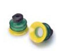
Fig. 4 - Polyurethane cup with dual hardness
More flexibility
Production flexibility for robots with a vacuum system is defined by the ability of handling a large variety of part types, minimized changeover times and easily adaptable capacity. The key vacuum system features for increased flexibility are independent suction cups or sectors of cups. If one or a group of suction cups misses the object, it does not affect the rest of the system. Smart patterns can work on many configurations. Palletizing and depalletizing are robot applications where sectors with suction cups in smart patterns are necessary.
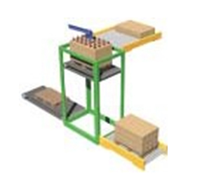
Fig. 5 – Suction cups in smart vacuum patterns are important for flexible palletizing/depalletizing.
A modular vacuum pump design can also increase the flexibility of a robot installation. It should be easy to up-size or down-size the vacuum capacity when needed. One example is the handling of cardboard material with varying permeability. Suctions cups that can handle several types of surfaces/objects mean less tool changes and increased flexibility.
Safety and product quality
For robot applications with a vacuum system, safety and improved product quality mean not loosing and/or damaging the handled part. These are some important vacuum issues for improved safety and product quality:
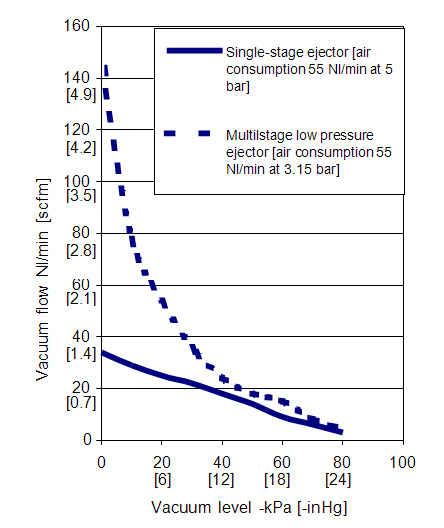
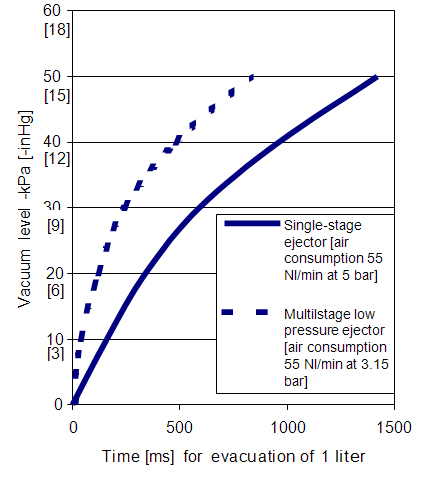
- Ejector nozzles should be designed for low and fluctuating feed pressures with preserved vacuum performance in order to achieve a reliable system. It is common with pressure fluctuations due to uneven utilization of compressed air in the plant. The compressor capacity is not always sized for the peak demand. Standard line pressure is 5-6 bar [70-90 psi] but temporary drops to 3-3.5 bar [40-50 psi] are not uncommon. Ejectors designed for 5 or 6 bar [70-90 psi] will lose a lot of capacity if the pressure drops below 4 bar [60 psi]. The result will be suction cups that drop the object handled.
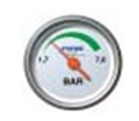
Fig. 6 – Ejectors should be designed for low feed pressures for a more reliable system.
- The vacuum pump(s) should continue to generate vacuum even if the power to the control valves is discontinued. In an airtight system (when handling sheet metal), vacuum pumps should be equipped with non-return valves. If the feeding of compressed air ceases, the system will maintain vacuum for a controllable time.
-
Suction cups with high friction on oily surfaces should be used. The ability to withstand high shear forces is critical in many robot applications. Proper material and cleat design are the determining factors.
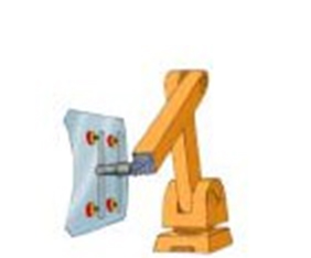
Fig. 7 – High material friction and cleats in the suction cups are necessary to withstand high shear forces.
- Suction cup cleats/foot pattern with the right design are also crucial for eliminating the risk of damages to thin products such as thin aluminum sheets in the car industry.
- Use abrasion-resistant material such as polyurethane in suction cups to avoid marks on sensitive products.
- Sensing vacuum for a clear signal to start robot motion should be measured as close to the suction cups as possible. Centralized systems with vacuum sensing positioned far away increase the risk of signals at false vacuum levels. Long vacuum hoses, bends, fittings and vacuum filters create pressure drops. The signal will come too soon and there will be a risk of insufficient lifting capacity in the suction cups when the robot motion starts.
- Flow-through silencers should be used on vacuum pumps. They do not stop the flow of particles and jeopardize the vacuum performance and system safety. Filter type silencers require periodic maintenance, otherwise they will reduce the vacuum performance when they clog.
Reduced manufacturing cost and positive impact on the environment.
Single-stage vacuum ejectors have poor energy economy and should not be used when air consumption is an issue. They can consume up to 300% more compressed air compared to state-of-the- art multistage ejectors used for the same task. An automatic air-saving system should be used in all airtight applications with a reasonable cycle time (> 1 second). The vacuum pump shuts off when a preset vacuum level is achieved. The pump restarts if the vacuum level drops below start-up level. For instance, up to 90% of the compressed-air consumption in a sheet metal handling application can be saved with an automatic energy-saving system.
A decentralized vacuum system with several smaller pumps close to the suction cups eliminates the risk of costly over-sized vacuum pumps in order to meet the productivity goals. The energy consumption can be reduced tremendously in many applications by changing to a more decentralized vacuum solution (a fully decentralized system has one vacuum pump per suction cup). Since the pressure difference between the atmosphere and the vacuum level in a system is small (<1 bar, [14.5 psi]), the influence of losses in a centralized vacuum system due to long tiny hoses, bends, fittings, valves, filters, etc., will be great and has to be compensated by increasing the size of the pump. A lot of people make the mistake of applying the same type of system-thinking when they design a vacuum system as when designing compressed air systems. The difference is that compressed air systems are far less sensitive to losses thanks to the high line pressure (5-6 bar [70-90 psi]). An analogy with electrical voltage can be made. Use high “voltage” for long transportations in thin wires and convert to low voltage as late as possible to minimize the losses! The conversion from compressed air to vacuum flow made by the ejector should be made as “late” as possible in the system.
Choosing an efficient multistage ejector will also reduce the noise level compared to non-efficient ejectors and, at the same time, create a more pleasant working environment. The noise level is lower because of more efficient utilization of the energy in the compressed air. The difference can be up to 10-15 dB(A), which means a lot for your ears.
CONCLUSION
In order to have success with a robot installation for material handling with vacuum, there are several things to keep in mind when the system is designed and dimensioned. Piab’s experience is that too many robot integrators spend too little time trying to optimize the vacuum system. The link between the vacuum system and things such as productivity gain, system safety, flexibility and manufacturing costs, is stronger than many of us believe. However, simple measures such as choosing multistage low-pressure ejectors instead of conventional ejectors, carefully selecting suction cup design and material and also decentralizing to a greater extent will improve the conditions for a successful robot implementation.
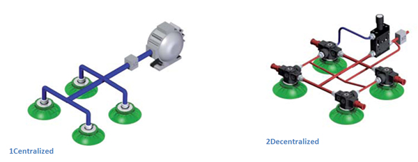
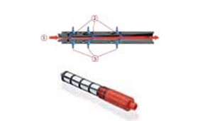
Fig. 1 &2 - In many applications several small pumps replacing a centrally placed pump will reduce the energy consumption to half by eliminating vacuum losses.
REFERENCES
(1) Antony Barber; “Pneumatic Handbook 8th Edition”, ISBN 1 85617 249-X, 1997.
The content & opinions in this article are the author’s and do not necessarily represent the views of RoboticsTomorrow
Featured Product

