In recent years, there have been many demands for equipment with high productivity to have a system that retains positioning information, even after the main power supply is turned off.
Development of Battery-Free Multi-Rotation Absolute Encoder
Contributed by | Orientalmotor
In recent years, greater accuracy and better reliability are demanded of motors, especially motors used in critical positioning applications. Such systems typically utilize encoder feedback with battery backup mounted on the motor, allowing it to perform closed loop control. However, since the battery frequently needs to be replaced, a maintenance-free absolute encoder is in high demand. From these requirements, a battery-free, multi-turn absolute encoder was developed. The AZ Series, a closed loop system, adopted this type of sensor and is currently on the market today.
Introduction
In recent years, there have been many demands for equipment with high productivity to have a system that retains positioning information, even after the main power supply is turned off. Motors used in such equipment (encoders with a battery backup system that retains positioning information of multiple rotations by using batteries) are widely used. Oriental Motor has incorporated this system into its products, such as the servo motor package and closed loop motor package.
However, the retention period of positioning information after losing the main power supply depends heavily on the capacity of the battery. Even if a battery is fully charged, it lasts for 2 weeks maximum on a motor with an encoder. Under normal use, leaving the main power supply turned off until the battery is completely drained, does not happen often. For this reason, users usually do not have to charge the battery frequently. A home position needs to be readjusted when the product is transported long distances or overseas or if it is not used for a long period of time. Furthermore, regulations for batteries during transportation have become far stricter and therefore, it is difficult to trans- port products while being connected to batteries. Also, because batteries generally last for 3 to 4 years, they need to be replaced periodically. Every time a battery is replaced, positioning information needs to be reset as well.
Due to these problems with the battery backup system, the demand for multi-rotation absolute encoders has increased. Therefore, the mechanical multi-rotation absolute sensor, which is incorporated with the gear mechanism, was devised. However historically, the structure of a mechanical sensor was very complex. It was expensive and large in size. For these reasons, the mainstream sensor, even today, is the battery backup system. Oriental Motor therefore started designing the mechanism that employs high- precision resin parts, while focusing on the aspect of a compact body. By incorporating the magnetic sensor, which has rapidly progressed in recent years, Oriental Motor has successfully developed a multi-rotation absolute sensor that is compact and affordable (patent pending). This is called the "Mechanical Absolute Sensor" (Refer to Figure 1), and it is featured on the AZ Series.
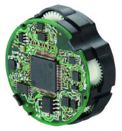
Fig 1 - Exterior of Mechanical Absolute Sensor
The AZ Series, equipped with the Mechanical Absolute Sensor, not only inherits characteristics of the such as being "Tuning-Free" and having "High-Efficiency", but also realizes the multi-rotation absolute system without batteries (Refer to Figure 2).
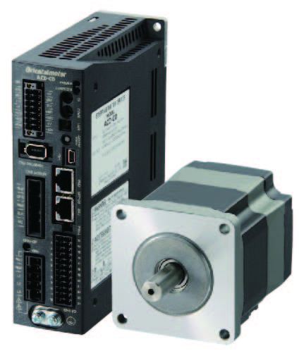
Fig 2 - AZ Series
Mechanical Absolute Sensor: Principle of Position Detection and Structure
The Mechanical Absolute Sensor detects coordinates within 1 rotation (360°) with a magnet installed at the center of the motor shaft and a magnetic sensor installed on a circuit board, which is placed directly above the magnet. This is a special kind of magnet which has the magnetization surface of 2 poles at the center, and multi-polar magnetization surfaces at the outer periphery (Refer to Figure 3). A rough coordinate is detected by reading the direction of magnetic flux, which comes out of the magnetization surface of 2 poles at the center. At the same time, the coordinate is combined with the phase difference of magnetic flux, which is detected from the multi-polar magnetization surfaces at the outer periphery. This is to calculate accurate position coordinates.
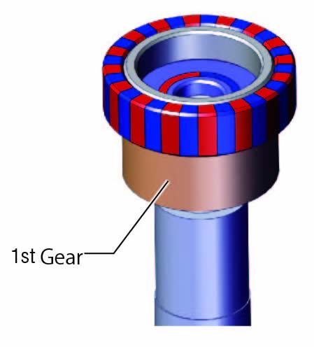
Figure 3 - Magnet Installed at Motor Shaft Center and the 1st Gear
The directions of magnetic flux of the magnet installed at the center of the motor shaft and the magnet installed in the gears placed around the motor shaft are read to detect the multi-rotation coordinates. One gear (1st gear) is placed at the motor shaft at the center, and parallel to the 1st gear, 2 columns of gears are placed. The first column is the gear with two-level configuration (1st/2nd gear, 2nd/3rd gear), and the second column is the gear with one-level configuration (1st/4th gear) (Refer to Figure 4).
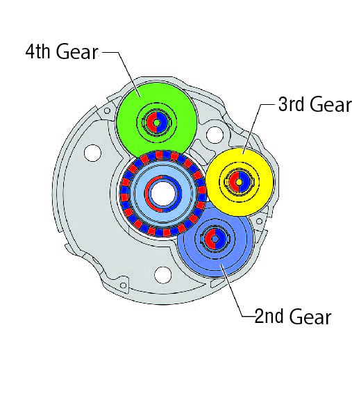
Figure 4 - Installation Conditions of Gears and Magnet
Each gear consists of different tooth counts and therefore, the phase differences between gears change every time the motor shaft rotates. By utilizing the phase differences, which are caused by the ratio of teeth numbers, the gear phase difference is detected in increments of 1 tooth (1 pitch). Based on the combination of phase differences, the multi-rotation coordinate is calculated (Refer to Figure 5).
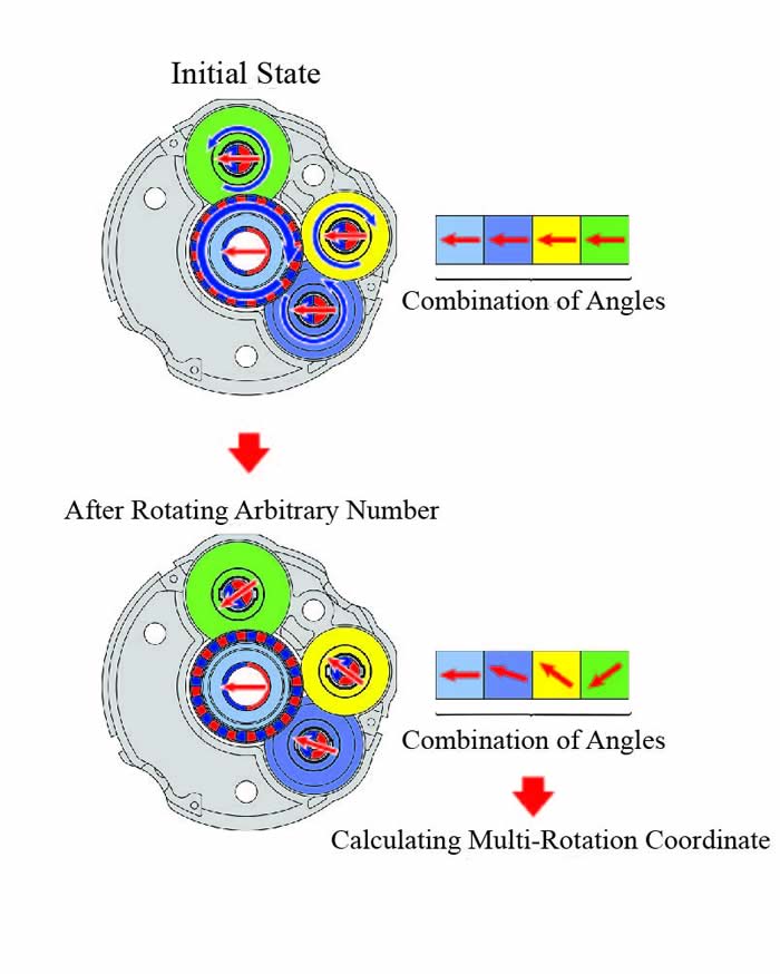
Figure 5 - Principle Image of Multi-Rotation Coordinate Calculation
It is possible to detect backlash as long as it is within 1 pitch. However, besides backlash, errors in coordinate detection can be due to the interference of magnetic force when multiple magnets are placed too close to one another, or caused by parts accuracy malfunction. Considering these aspects, the designed value of backlash is even smaller than 1 pitch of a gear.
The phase differences of all gears are designed to return to their initial states after rotating 1,800 times. With this feature, it is possible for the Mechanical Absolute Sensor to detect multi-rotation coordinates for up to 1,800 rotations. The number of 1,800 rotations, which are the detectable multi-rotation coordinates, is the common multiplier of gear ratio variations for Oriental Motor products and thus, it makes it easy to control coordinates at the gearhead output shaft.
The following example is used to further explain the multi-rotation detection principle:
Let's assume that there are 9 teeth on the drive side gear, and 10 teeth on the non-drive side gear. When the drive side gear rotates once, the non-drive side gear rotates 324°, which is 36° (360°/10 ) less and is the angle of one tooth. When repeating the rotations, the positioning relationship of these gears shift 36° per rotation, and they return to their initial states after 10 rotations.
When using the combination of these gears, the multi-rotation coordinates for 10 rotations can be detected. The principle of the detection of multi-rotation coordinates from phase differences of several gears is similar to the principle of how to make the timing from the combination of angles (phase differences) of the hour hand, minute hand and second hand of a clock.
Due to the following reasons, resin materials are used for the gears and the sensor enclosure:
The Mechanical Absolute Sensor employs magnets and a magnetic sensor.
If magnetic materials are used for the structure, they interfere directions of magnetic flux and thus, position detection becomes very difficult. Because resins are non-magnetic materials, they do not interfere with detection accuracy.
Resins have a self-lubricating characteristic and are excellent for wear and abrasion resistance.
Compared to precious metal materials, resins can make the motor mass, including the sensor, become lighter, and the inertia moment of the gear mechanism become smaller.
In order to make the sensor itself compact, its structure was designed to make the circuit board mounted with a magnetic sensor become closer to the gear mechanism. When using conductive materials, it may cause the electric circuit to be shorted out if frictional dust is generated.
The structure would become too complicated when trying to prevent frictional dust from entering into the electric circuit resulting in increase of parts cost and worsening of productivity.
Durability of Mechanical Absolute Sensor
As explained earlier, the Mechanical Absolute Sensor utilizes the multi-rotation position detection by employing the gear mechanism. The gears in the Mechanical Absolute Sensor are used for the purpose of multi-rotation position detection by creating phase differences among the gears, but not for the purpose of power transmission. For this reason, they are driven under nearly no loads. For the materials of these gears, resins, which have a self-lubricating characteristic and are excellent for wear and abrasion resistance, and the grease exclusively for resins, are used for high durability.
From the standpoints of abrasion resistance and impact resistance, the following tests of uni-directional continuous operation and instantaneous bi-directional operation were conducted, in order to confirm high durability of the gears.
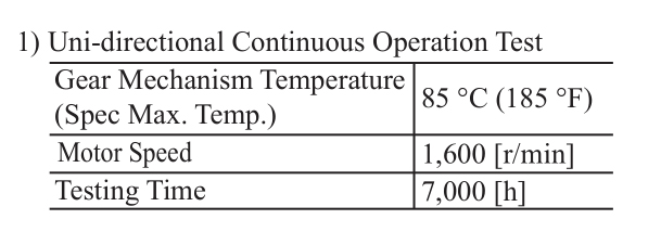
By measuring backlash within the specified period under the above conditions, the gear's tooth surface wear volume was tested. As a result, no deterioration with time for backlash was detected.
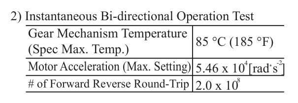
The test was conducted under the conditions above. Just as the test result from Test 1, no increase of backlash between gears, or no deterioration with time was detected.
Features of the AZ Series with Mechanical Absolute Sensor
The AZ Series is a closed loop motor package equipped with the newly developed Mechanical Absolute Sensor, which uses the multi-rotation absolute system without batteries. The Mechanical Absolute Sensor detects absolute coordinates, enabling the motor to have a home position. Therefore, it is not necessary to do return-to-home operations. Even if a return-to-home operation is required, an external sensor is not needed since the motor has its own home position. In general, when conducting a highly accurate return-to-home operation with an external sensor, it is necessary to do it at very low speed while considering the sampling cycle of the sensor's ON/OFF detections. Depending on circumstances, this takes a long period of time. Also, in order to improve the return-to-home accuracy, it takes a little ingenuity, for example, by combining the external sensor with the Z phase signal (Refer to Figure 6), or using a return-to-home push- motion operation.
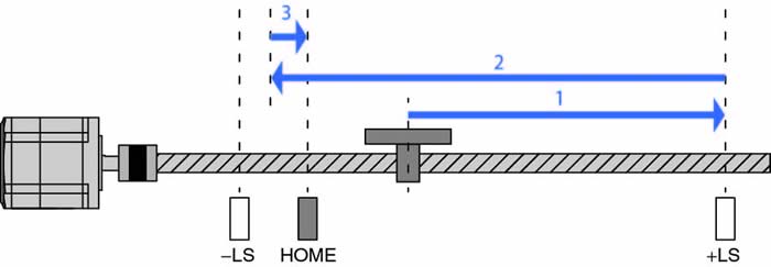
Figure 6 - Home Detection with a Conventional Control Motor
When using the AZ Series product, a user does not need to worry about speed or sensor accuracy. The speed limit of the return-to-home operation can be freely set within the range that the motor can drive. Also, it is possible to conduct a return-to-home operation while retaining the positioning accuracy of the motor (Refer to Figure 7).

Figure 7 - Home Detection with the AZ Series
In addition, for a conventional control motor, an optical sensor is often used as a sensor (limit sensor, etc.) installed on the equipment side. However, oil mist or dust in the air sometimes causes an optical sensor to malfunction or recognize falsely. By using the AZ Series product, a need for a sensor is eliminated, resulting in having less impact of sensor related failures on the entire equipment. The elimination of a sensor is not only cost saving for the sensor itself, but also for elimina- tion of wires to connect to the sensor. Also, the labor has been eliminated in wiring the sensor. When setting an equipment home position with an external sensor, it is necessary to install the sensor at the targeted location, which may require subtle adjustments of the distance. On the contrary, the AZ Series product can easily select and set any given position as home position by using the "Home Position Reset Function". With the AZ Series, a user can not only avoid having equipment adjustments, but also eliminate costs required for the adjustments. Furthermore, because it requires no batteries, there is no need for battery replacement, resulting in cost reduction. In addition, there is no need for having an extra space for the battery replacement. Also, unlike the battery backup system, which has time limits on the retention period of positioning information, the AZ Series product can retain positioning information almost permanently. Because the motor can retain positioning information, the information is secured although the equipment is disassembled, detaching the motor and driver completely. When transporting large-size equipment, for example, even if the control box and gear mechanism are disassembled and then assem- bled after being transported, its positioning information is securely stored and thus, there is no need to reset the coordinate.
Summary
The AZ Series equipped with the newly developed Mechanical Absolute Sensor allows for the battery-free multi-rotation absolute system to be used. It contributes to cost reduction of the overall equipment for users by eliminating an external sensor and maintenance costs. While inheriting characteristics of high reliability and efficient technology through the closed loop control, which were developed with , the AZ Series offers "easy, high performance and high functionality", such as sequence functions and various monitoring functions. The product lines that feature characteristics of this sensor will be further developed in the near future.
The content & opinions in this article are the author’s and do not necessarily represent the views of RoboticsTomorrow
Featured Product
