This document presents a new optimized integration of a compact gear reducer, specific designs of BLDC motor and magnetic absolute position sensor for high torque per volume demanding applications.
 Compact Mechatronic Drive for Robotic Applications
Lionel Billet, Michaël Delbaere, Tommy Pinel | Moving Magnet Technologies SA
I. ACTUATORS FOR DISABLED PEOPLE AND THEIR SPECIFICITIES
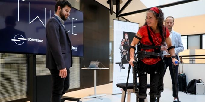
Emerging from the field of robotics, powered exoskeletons are new solutions to enable paraplegic people to walk again.
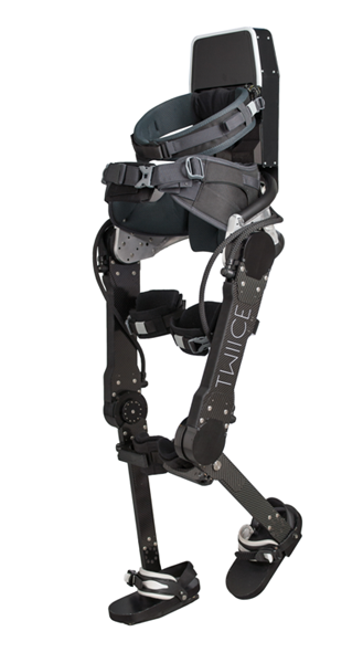
Figure 1. TWIICE from Rehassist, front viewSome
Specifications of exoskeleton actuators are common to other robotic application like compactness, high active torque -say 100Nm maximum - and a quite small diameter -say less than 100mm- for an easy integration. Other needs are more specific for the assistance of disabled people, as explained in reference [1] and [2]:
• Small length – the disabled user still needs the assistance of his arms, so the actuator must be as thin as possible so as not to interfere with the crutch movement – 60mm maximum for example.
• High tilting torque - the load cannot be considered as a pure torque on the rotation axis, when the disabled person is walking in a not fully balanced manner the tilting torque can reach values as high as the active torque of 100 Nm, and contrary to common industrial actuators or reducers additional bearings cannot be integrated.
• Reversibility is needed for the initialization phase or temporary storage, or to allow defect management.
• Reading of the output position at power up allowing the disabled person to easily set up the exoskeleton in a pre-programmed position.
• Mass- as any extra mass will be a burden for the disabled person, a target of 1.5kg was fixed for one actuator.
II. MOTOR DESIGN
As required in general robotics, the brushless motor selection criteria were: low cogging torque, high torque density and low inertia. The two last parameters can be seen as contradictory as the torque must be optimized to increase the radius of action of the motor magnets and therefore increasing the rotor inertia. To these criteria is added a specific need for a low profile motor, coils included, and a relatively large inner diameter of the rotor to allow specific integrations of the reducer.
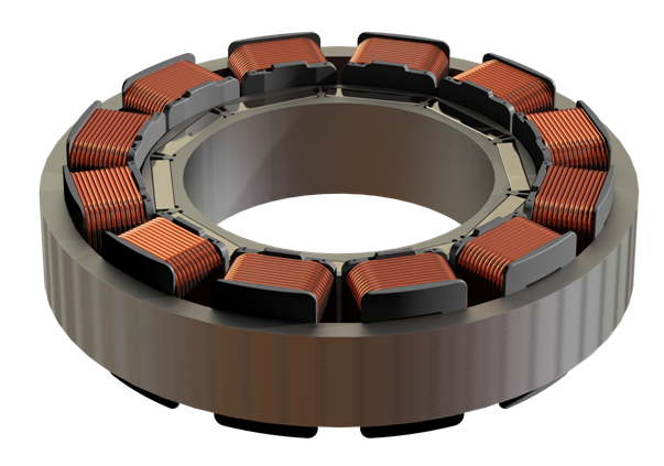
Figure 2. Example of a 12 coils BLDC motor
The choice of off-line winding was a compromise between higher performances and mechanical simplicity and robustness, but as seen in the measurements the loss of torque is perfectly acceptable. Thanks to the straight teeth that show a low saturation behavior, we observe only a decrease of 5% of the torque versus the current slope measured at the maximum operating torque of the BLDC motor – 3 Nm -, even using very common silicon iron material for the stator core. The volume of the motor is extrapolated based on the thermal static measurement and from the worst typical duty-cycle (typically it corresponds to when the disabled person is climbing stairs).
III. REDUCER DESIGN
The aim of the reducer is to develop a high active torque within the most compact volume. The epicycloid gear reducer is too bulky to be used in this application due to the high required number of stage to obtain a gear ratio superior to 1:40 and the fact that efficiency is sensitive to the number of stage [3]. Besides the gear reducer system must reach a high reduction ratio with only one stage. Finally, the study led to a gear ratio of 1:51, as a compromise between torque needed at the motor and reducer maximum speed. The whole reducer system is validated with FEM analysis.
IV. SENSOR
One particular request of these applications is the need of an absolute sensor for opening the exoskeleton, and for double checking the motor commutations. The normal procedure is to remove the exoskeleton from its package and start the initialization to allow the system to be in the mounting shape, the start position being unknown. An encoder, as commonly used, is insufficient for this phase as the power off position can be mechanically modified due to the reversibility of the system. Our proposal is a new magnetic sensor, with some specific integration properties described in more details in the next chapter.
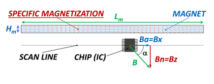
Figure 3. MMT sensor design for linear motion and continuously rotating magnetization.
The sensors are based on magnetic field direction measurement leading to more straightforward designs, only based on one polarized magnet with angular or linear displacement in front of a Hall chip. For an angular position sensor, the designer can simply choose a well-proven end-of-shaft configuration from a toolbox, but when the mechanical constraints prevent such an integration, e.g. due to a hollow shaft configuration, an off-axis angular measurement is also possible, using a 1-pole or 2-pole magnet tile.
However, use of such standard approaches is limited, due to a lack of flexibility in terms of mechanical integration. One such example is to be pushed to operate at medium to large air gaps between the sensor IC and the moving magnet in order to reach the required standard accuracy while keeping the sensor robust against probe-to-magnet distance variations. Such mechanical constraints result in the need to use powerful and/or bulky magnets in order to ensure operation at these large probe-to-magnet distances. In other words, the standard approaches may suffer from a lack of compactness, poor integration. Assessing the position sensor requirements of the current and future robotic industry shows the need for an advanced position sensor technology with the following key features:
• The sensor must cover a wide range of short to long mechanical strokes (a few degrees to 360°)
• It must be capable of operating from small to large mechanical gaps (2 mm to 10 mm)
• It should be robust against mechanical tolerances.
• It should be immune against typical magnetic perturbations (> ± 12.5 G).
• Integration should be easy and versatile.
• And finally, the cost should be affordable.
Taking these requirements and the intrinsic issues of the standard design approach into account, MMT has developed a unique magnetosensitive position sensor technology based on a moving magnet with a specific magnetization and a direct angle IC which can be a Hall-effect or a magnetoresistive probe (Figure 8).
The MMT sensor principle is based on a continuously rotating magnetization, resembling a continuous Halbach array. The direction of the magnetization vector varies inside the magnet along the direction of the stroke in a very linear way while its amplitude stays constant according to the magnet saturation. With such a magnetization pattern the magneto-sensitive IC will detect magnetic components which are intrinsically sinusoidal even for small probe-to-magnet distances. It therefore implies a very linear magnetic angle variation along the mechanical stroke. For example a rotary sensor with a mechanical stroke of 80° can have a total magnetic angle variation of 330° which cannot be reached with conventional magnetic angle measurement sensors. Finally, the rotating magnetization in the magnet volume concentrates the magnetic flux density on the side of the magnetic sensor chip, contrary to a standard design, where the flux density is weaker since it is distributed over both faces (Figure 5). This allows tailored position sensor optimization either by downsizing the magnet, or improving its robustness against external magnetic stray fields or its sensitivity to other magnetic mechanical parts of the actuator.
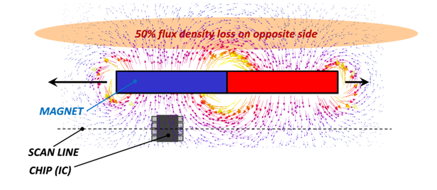
Figure 4. state of the art angular magnetic sensor flux lines
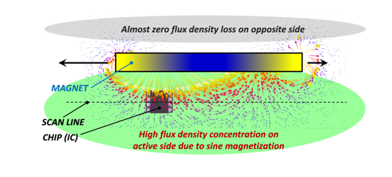
Figure 5. MM113 flux lines
Moreover, the sensor cannot be considered alone in our actuators as it faces multiple risks of pollution, say a cross talk, coming from the other sources of magnetic fluxes
• the motor rotor with magnets
• the rotor magnetic encoder for motor commutation
• and the coils of the stator
In contrast, the rotor magnetic encoder must be shielded from the flux generated by the absolute sensor. It is generally easily solved in actuators since the absolute sensor is located close to the output side, opposite the motor, on an independent PCB. But this assembly generates unused volumes and multiple wire connections.
V. GENERAL INTEGRATION
The specificity of this integration with high challenge in term of compactness was to partially locate the reducer in the inner free diameter of the motor rotor, and to locate the absolute sensor magnet in a way we can measure the magnetic field using a unique PCB (also used for the rotor position determination and for motor phase connections).
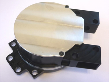
Figure 6. Actuator for exosqueletton, view from the PCB side
Therefore the whole system can be equipped with a unique PCB where motor phase connection are done - the rotor angular position being measured with a Hall probe as in a start of the art BLDC motors .
The unique PCB and low connection number is one of the trends coming from MMT’s automotive background.
VI. RESULTS
A comparison can be made now between the first exoskeleton prototype and the new system. One good comparison parameter can be the energy used by the BLDC motor coils to generate the needed torque, but also negatively heating these coils by Joule losses. The link between torque and Joule power is commonly named motor constant Km, in Newton meter by square root of Watts, with the useful characteristics to be independent of coil winding choice or driver voltage specification.
The first exoskeleton shown in figure 1 associates a BLDC motor with a torque constant of 58mNm/√W, a belt (gear ratio 1:1.4) and a strain wave reducer (gear ratio= 1:100). This system was very effective with a disabled user of about 60kg, and provided a large batch of data on torque, speed and thermal behavior.
The advantage of the new system is obvious when calculations are done with a theoretical 100kg user and the same test path. Taking the same mechanical efficiency of 70% for the two reducers we generate the following curves of lost energy in motor coils on a given user step.
Then simulations are done with the new system based on a 1:51 gear ratio and an BLDC motor with a Km=216mNm/√W.
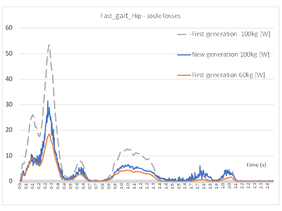
Figure 7. Joule losses measurement with the current system gear ratio 1:140 and a 60kg user (lower curve) , calculation with a 100kg user (upper curve) and the current exoskeleton, and same movement with the new actuator and a 100kg disabled person (center curve).
The new actuator uses a far lower energy than the first exoskeleton actuator for the same specification of a 100kg user, almost half, and thanks to its larger motor volume in the new actuator the extra Joule losses will be easily dissipated.
VII. CONCLUSION
This compact actuator will help disabled people but also could be used for any field of robotics where compactness, high mechanical requirements and robustness are needed. The target of 300Nm/dcm3 was reached during the prototype measurements. VIII. MMT Moving Magnet Technologies (MMT) has been building a success story for more than 25 years based on its unique expertise in developing innovative electromagnetic solutions in the field of position sensors, direct drive actuators and electric motors for high end mechatronic applications. Since 1995, MMT is a part of the Sonceboz group.
Today MMT has about 45 employees including more than 30 PhDs and engineers focused on the development of innovative electromagnetic solutions. Our team excels in applying the latest finite element analysis software tools for magnetic simulations and dynamic modeling. We also have prototyping and test capabilities for validating our developments. A team of electronics engineers develops the necessary hardware and software to drive our motors and actuators. MMT strives for being recognized as a worldwide leader and essential partner in the field of electromagnetism applied to mechatronics. Our activities are based on 3 main pillars: R&D, engineering and licensing. The goal of our R&D specialists is the development of innovative electromagnetic technologies: we hold 200 valid patents so far, and 3 to 5 new patents are applied for every year. This includes collaborations with renowned universities and high level technical institutions.
ACKNOWLEDGMENT
The authors would like to thank the Rehassist and especially Prof. Bouri for the support in this project.
REFERENCES
[1] An Assistive Lower Limb Exoskeleton for People with Neurological Gait Disorders, A. Ortlieb, R. Baud, M. Bouri, H. Bleuler, Int. Conference Rehabilitation Robotics, London, 2017
[2] • TWIICE -- a Lightweight Lower-Limb Exoskeleton for Complete Paraplegics, T. Vouga, R. Baud, J. Fasola, M. Bouri, H. Bleuler, Int. Conference Rehabilitation Robotics, London, 2017
[3] D.R. Salgado, J.M. del Castillo , “Analysis of the transmission ratio and efficiency ranges of the four-,five-, and six-link planetary gear trains” Mechanism and Machine Theory 73 (2014) 218-243.
[4] Tongliang Liu, Bindi You, Peixiang Wang, Binjiu Yang, Lei Liu , “Heat-Structure Coupling Analysis of Harmonic Drive under Different Thermal Loading” International Journal of Control and Automation Vol.8, No.11 (2015), pp.201-210.
[5] B.Routh, R.Maiti , “Effects of pressure angle on initial tooth contacts pattern in conventional harmonic drive” International Gear Conference (2018) Vol.1, 478-487.
The content & opinions in this article are the author’s and do not necessarily represent the views of RoboticsTomorrow
Featured Product