Interpolation is a mathematical technique used to estimate unknown values that lie between known data points. Interpolation helps transform raw sensor data into stunning, full-color images in embedded vision systems.
Prabu Kumar | e-con Systems
In imaging, interpolation is a mathematical operation that is used to perceive a colored image as seen in the real world. Interpolation also drives the advanced image processing capabilities of ISPs.
Here is a little glimpse into how interpolation came into the camera scene. To capture an image, we need photons from a light source, lens, sensors, and memory to store the data. But to capture color in the images, these aren’t enough. Image sensors are comprised of many individual photosensors, all of which capture light. These photosensors are natively able to capture the intensity of light but not its wavelength (color).
To tackle this problem, image sensors were overlaid with something called a “color filter array” or “color filter mosaic.” This overlay consists of many tiny filters that cover the known pixels and allow them to render color information. However, these color filters over the sensors will allow only a single color to pass through it, that is, either R, G or B.
In order to obtain all these colors in an image despite the single color filter, prisms were used in the earlier days to split the color coming from a light source. Prisms help obtain the primary colors R, G, and B through diffraction. Multiple sensors placed in different directions were used to capture the colors obtained through prisms, making the cameras bulky and complicated. However, this method allowed us to capture all three colors in the image obtained.
Then came the modern cameras with CMOS sensors. CMOS sensors came with a Bayer filter array that enabled the capturing of color using a single sensor. However, one major drawback was that the Bayer filter CMOS camera capture only one color element per pixel, as the filter allows only one color element to pass through it. This results in an incomplete color data. This is where interpolation comes into use. Here, interpolation operation can help estimate the missing colors, thereby completing the image.
![]()
Figure 1: Bayer filter in CMOS camera capturing only one-color element per pixel

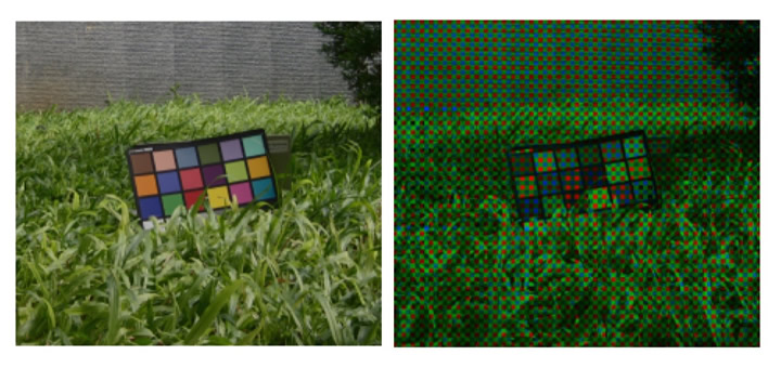
Figure 2: (a) Original Image (at 200%). (b)What Your Camera Sees a Through Bayer Array
Read the blog to learn the basics of interpolation, its significance in imaging, how it is implemented in an Image Signal Processor (ISP), and the artifacts associated with it.
What is Interpolation?
Interpolation is a mathematical technique used to estimate unknown values that lie between known data points. In simpler terms, it bridges gaps in data by predicting intermediate values. While interpolation focuses on filling gaps within the known range, extrapolation deals with predicting values outside the known data points.

Figure 3: Mathematical/Graphical Representation of Interpolation
In the context of imaging, interpolation helps reconstruct missing colour and intensity information in images, playing an important role in creating visually accurate outputs.
What Is an Interpolation Kernel?
A kernel can be thought of as a weighted function applied to neighbouring pixel values to compute an interpolated value. Essentially, it’s a mathematical tool that “spreads out” or weights the contribution of known data points to predict or calculate unknown ones.
For example, in a grid of pixels, if you have data values at certain points and need to estimate the values in between, kernels guide how the neighboring points influence the calculation. Kernels vary in complexity, from simple linear functions to advanced techniques using waveforms or gradients, depending on the accuracy and smoothness required.
In tasks like resizing or demosaicing, kernels define how the missing pixel values are computed. The choice of kernel impacts the following:
- Sharpness: Some kernels prioritize preserving edges and fine details.
- Smoothing: Others focus on minimizing noise and blending transitions.
- Accuracy: Advanced kernels adapt dynamically to image content, reducing artifacts and improving color fidelity.
Types of Kernels and Their Characteristics
Gaussian Kernel: A Gaussian kernel applies weights that follow a bell-shaped curve. Pixels closer to the point being interpolated will have higher weights, while those farther away contribute less. This kernel is primarily used for smoothing and noise reduction. Gaussian kernel has a smaller area of influence, leading to less precision in capturing sharp edges or transitions. This makes it Gaussian kernel less effective for high-frequency details.
SinC Kernel: SinC kernel is based on the sinC function. It combines sine waves to approximate missing values. SinC kernel’s influence extends over a larger area compared to Gaussian kernels, capturing more complex patterns in oscillatory data. This Kernel is ideal for high-precision tasks, such as upscaling images or handling complex textures. SinC kernels provide sharper results than Gaussian kernels.
Bilinear Kernel: Bilinear kernel extends linear interpolation into two dimensions. It uses the values of four neighbouring pixels in a grid to estimate the value of a new pixel. It is used for simple image scaling tasks where computational efficiency is a priority. While being very effective, it may introduce blocky or overly smooth regions in detailed images.
Bicubic Kernel: Bicubic interpolation is an enhancement of bilinear interpolation. It uses the gradients (rate of change) of known data points, applying cubic polynomial equations to estimate smoother transitions. This kernel is preferred for high-quality image scaling, as it preserves sharpness and natural gradients. Bicubic kernel balances computational cost and image quality, making it widely used in image processing for OEM cameras.
Techniques of Interpolation in CMOS Sensors
Various interpolation methods serve distinct roles in camera systems, each with its trade-offs between computational efficiency and image quality. Let us look at the most commonly used interpolation techniques used in CMOS sensors.
Nearest-Neighbor Interpolation: Nearest-neighbour interpolation is the simplest approach that copies values from nearby pixels. It is a faster method but can result in blocky, low-quality images, making it unsuitable for premium OEM applications.
Bilinear and Bicubic Interpolation: These interpolation methods consider two or four neighboring pixels. This helps in attaining smoother transitions for better image quality. Bicubic interpolation is particularly favored in balancing sharpness and smooth gradients, which is useful in embedded applications like robotics and autonomous navigation.
Lanczos Resampling: Lanczos resampling is a higher-order technique using sinC-based kernels, it offers superior edge detail, making it ideal for surveillance or medical imaging cameras where precision is important.
Adaptive Methods: Techniques like Variable Number of Gradients (VNG) or Adaptive Homogeneity-Directed (AHD) interpolation adapts dynamically to image content. These are widely adopted in demosaicing algorithms to reduce color artifacts, ensuring natural and accurate image reproduction.

Figure 4: Visual comparison of different interpolation methods. (a) Nearest neighbor. (b) Bilinear. (c) Bicubic. (d) Original HR image (4x)
How ISPs Use Interpolation
Interpolation in ISPs (Image Signal Processors) serves various purposes, let’s explore a few of them.
Resizing Images: In ISP’s interpolation is used to resize images. For example, resizing a 4×4-pixel array to 8×8. For this ISP’s use Linear or bilinear interpolation that can help smoothen the output. Nearest neighbor interpolation isn’t used for this as it can lead to sharp edges (pixelation).
Demosaicing: Interpolation is used to convert raw sensor data into a full-color image, which is called as demosaicing. This can be done using weighted interpolation, which can determine the missing values for each color channel based on neighboring pixel values.
Deblurring: Ensures image sharpness during interpolation by cutting and realigning edges. Techniques like edge-directed interpolation and constant hue interpolation further refine the output.
Bicubic Interpolation: Bicubic interpolation improves upon bilinear by considering gradients, which represent the rate of change between data points. This allows for smoother transitions and more detailed reconstructions.
Artifacts Caused by Interpolation
Despite its benefits, interpolation introduces certain artifacts:
Color Merging: When two colors blend, dark spots may appear between transitions. This occurs because cameras interpret contrast linearly, whereas human vision is logarithmic.
Data Storage and Compression: Camera’s store squared values of pixel intensities to match the logarithmic perception of human eyes, especially in darker regions. While this approach saves space, it can lead to slight deviations in brightness.
Combatting Demosaicing Artifacts in OEM Cameras
Demosaicing, a pivotal step for color reconstruction, is prone to challenges such as color moiré patterns and zippering artifacts in high-frequency regions. OEM cameras tackle these challenges with:
Gradient-Based Methods: These prioritize low-gradient areas for interpolation, minimizing distortions.
Edge-Aware Techniques: By detecting and preserving edges, such methods ensure that critical details remain intact, particularly in automotive or industrial cameras where accuracy can influence decision-making.
Modern advancements have unified super-resolution and demosaicing, addressing shared issues like aliasing, and have been implemented in multi-frame video reconstruction. This dual-purpose approach enhances the performance of cameras used in dynamic environments, such as drones or delivery robots.
The OEM Advantage: Optimized for Industry Needs
For an OEM camera manufacturer, the choice of interpolation algorithm isn’t arbitrary. It must align with:
Application-Specific Requirements: Surveillance cameras benefit from Lanczos resampling, whereas bilinear or bicubic techniques are better suited for high-speed operations like warehouse robotics.
Computational Constraints: Cameras integrated with low-power systems may favor efficient methods like bilinear interpolation to maintain real-time processing.
Sensor Design: High-quality CMOS sensors with advanced color filter arrays (CFAs) like panchromatic CFAs complement linear interpolation methods for superior results.
By fine tuning interpolation strategies to these factors, OEM cameras achieve utmost precision, contributing to the success of diverse industries.
Explore e-con Systems’ OEM Cameras Suitable for Your Embedded Vision Application
e-con Systems is an industry pioneer with 20+ years of experience designing, developing, and manufacturing OEM cameras.
We recognize embedded vision application’s camera requirements and build our cameras to best suit the industry demands.
We also provide various customization services, including camera enclosures, resolution, frame rate, and sensors of your choice, to ensure our cameras fit perfectly into your embedded vision applications.
Prabu Kumar is the Chief Technology Officer and Head of Camera Products at e-con Systems, and comes with a rich experience of more than 15 years in the embedded vision space. He brings to the table a deep knowledge in USB cameras, embedded vision cameras, vision algorithms and FPGAs. He has built 50+ camera solutions spanning various domains such as medical, industrial, agriculture, retail, biometrics, and more. He also comes with expertise in device driver development and BSP development. Currently, Prabu’s focus is to build smart camera solutions that power new age AI based applications.
The content & opinions in this article are the author’s and do not necessarily represent the views of RoboticsTomorrow

e-con Systems
e-con Systems® develops complete embedded vision solutions—including OEM cameras and edge AI compute platforms. With 20+ years of experience and expertise in embedded vision, it focuses on delivering vision and camera solutions to industries such as Robotics, Mobility, Medical and Life Science, Agriculture, Intelligent Transport Systems, Sports Analytics and more. e-con Systems' wide portfolio of products includes MIPI camera modules, GMSL cameras, USB 3.2 cameras, Depth cameras, GigE cameras, HDR cameras, low light cameras, and more. Our cameras are currently embedded in over 350+ customer products, and we have shipped over 2 million cameras to the United States, Europe, Japan, South Korea, and many other countries.
Other Articles
Deep Dive into integration challenges of ONVIF-compliant GigE cameras and how ONVIF enhances interoperability
Importance of Global Shutter Cameras for Industrial Automation Systems
What Is The Role of Embedded Cameras in Smart Warehouse Automation?
More about e-con Systems
Featured Product


